Study of the Structural Properties of Lead-Doped Tio2: Pb and Iron- Doped Tio2:Fe Titanium Dioxide Powders
- 1. Department of Physics, Faculty of science, Tishreen University, Syria
Abstract
In this research, a group of samples were prepared from pure titanium oxide compound doped with lead in different ratios according to (x = 0.2 - 0.5 - 0.7 - 0.9 g) and other samples doped with iron at a rate of x = 10% by grinding with metal balls and for different rotational speeds. 250 rpm for the pure sample and (250, 300, 350, 400) rpm for the ratio x = 10% and for a mixing period of up to 5hr, it was found that the iron-doped compounds crystallize according to the quaternary structure at the aforementioned preparation conditions. The XRD diagrams show the change of the structural properties of the different TiO2 samples with impurities and the method of preparation due to the effect of positive ions (Fe3+) and (Pb4+), where we notice that the crystal size decreases when iron ions are introduced into the structure of titanium oxide and It increases when the lead ions are subtracted, then it increases again with the increase in the rotational speed and decreases when the ratio of lead doping is 0.7 g.
The results of the XRD showed the participation or non-participation of the samples of anatase and rutile of the tetragonal crystal system and brookite of the orthorhombic crystal system based on the titanium dioxide compound with different crystalline levels, and the preferred direction was (211) in all lead-doped and un-doped samples. For iron-doped and undoped samples for different spin velocities, it had a preferred orientation (101), and the relative strength, distance between crystal planes (d), crystal size (D) and lattice parameters (a), (b) and (c) phase cell volume (V).
Keywords
Powder, Titanium dioxide TiO2 doped with lead Pb, Structural properties, Physical properties, XRD, Ball milling grinding, Nano compounds
Citation
Khoudro A, Sater S, Kanjaraoi R (2023) Studying Study of the Structural Properties of Lead-Doped Tio2: Pb and Iron-Doped Tio2:Fe Titanium Dioxide Powders. JSM Chem 10(1): 1061.
INTRODUCTION
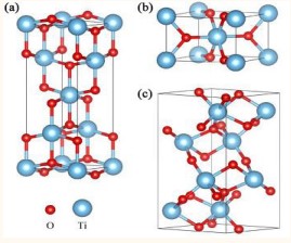
Titanium dioxide has gained great interest in international research laboratories due to its distinguished properties, and it is a multi-faceted compound used as a strong photocatalyst [1], capable of breaking down any organic compound when exposed to the sun [2-12], As well as the importance of titanium in biocompatible systems [13], thanks to the English chemist and geologist William Gregor who discovered the element titanium Ti in 1791 AD, on which many experiments were conducted that ended with the manufacture of titanium dioxide TiO2 with structural properties Characterized by three crystalline phases with three different crystalline phases, namely: anatase with a tetragonal crystal system, brookite with an orthorhombic crystal system, and rutile with a tetragonal crystal system as in Figure 1[14].
Thus, it can be used to purify water/wastewater and air, and in whitening teeth and fabrics [15], and thus in the manufacture of cosmetics and in many other industrial applications such as manufacturing electronic circuits, batteries, and solar cells [16] and in The field of chemicals such as hydrogen production because of its important physical and chemical properties, it has chemical stability and is chemically non-toxic[1,9,10,15-26], and is characterized by an energy gap Eg ranging between 3.04- 3.46 eV [27], and it has a high resistivity estimated at 1012 Ωcm at a temperature of 25C°, and it also has a high value for each of the static permittivity, transparency in the visible field, the refractive index and luminosity, which expands its uses as paint in All types of coatings and as a food additive to pharmaceutical materials [2-5,29-33]. We have chosen the elements Pb and Fe as impurities in the TiO2 compound, and each of the two impurities is added in a different manner from the other to the structure of the compound. We used the X-ray diffraction device (XRD) in order to study the structural properties in order to improve the physical properties and expand the areas of use of titanium dioxide, and many researchers have done experiments doping the compound with different chemical elements and compounds and tested it using each of the devices XRD, SEM, DRS, EDS, FTIR and others, which showed shifting the radiation absorption field from ultraviolet radiation to include raising the absorption efficiency of these rays as well as optical rays and narrowing the band gap and thus increasing photo catalysis [32], electrical
conductance and other electronic, physical and microscopic properties [2,3,5,7-10,12,14,15,27,34,35].
Our use of new preparation methods adds new references, tests and improvements to chemical Nano composites and other photo catalysts [18,36]. The mechanical-chemical methods received great attention in the field of photo catalysts, as their preparation time is very short compared to the traditional chemical methods, and they enable us to prepare effective nanomaterials in a wide range of uses, and the mechanicalchemical methods are environmentally friendly methods, they consume less energy, they are recyclable, and they are Dangerous solutions are rarely used [37].
EXPERIMENTAL METHOD
First: titanium dioxide compound doped with lead TiO2:Pb
We weighed powders of pure and lead doped TiO2 with different ratios according to (x = 0.2 – 0.5 – 0.7 – 0.9 g) Ti1-x Pbx O2 using solid-state interaction method [29] and [38], and it was mixed and crushed well using (Agate mortar and pestle) to turn it into powders very fine and then sieved through a sieve giving the size of the opening of the sieve 90 microns. The mixtures were ground for two hours for all powder samples in order to obtain a homogeneous and well-distributed powder. To remove moisture, the crushed samples were heated to 200°C by an incinerator, as all the preparation process took place in the physics and chemistry laboratories at the Faculty of Science at Tishreen University.
Second: titanium dioxide compound doped with iron TiO2:Fe
Devices and tools used:
1. Ball Mill/Industrial Ball Mill Type/Damascus Atomic Energy Commission.
2. X-ray diffraction (XRD) using the STOE STADI P Transmission/ German company which headquarter it in Germany
3. Scanning electron microscope SEM type VEGA2 TESCAN / Atomic Energy Commission in Damascus.
4. Specored S100 / Photodiode Array / Spectrometer / Atomic Energy Commission in Damascus.
Sample preparation: The samples were prepared by grinding with metal balls, where we used a chamber of size 25 (cm)3 of stainless steel containing ten steel balls, each with a mass of 4.06g and a size of 0.5236 (cm)3 (diameter 1cm) that can rotate at different speeds and for different times to grind and mix The raw materials needed to prepare the desired sample, where a quantity of the material to be prepared is placed inside the chamber so that the equation is achieved:
It is the weight of the raw material to be grinded and mixed from the compound (TiO2 ) to which iron is added. Therefore, for the x% mixing ratio of iron, this means that the mass of iron in the sample is equal to:
Thus, we prepared the samples shown in the following Table 1:
Table 1: Samples of pure titanium dioxide and iron alloys prepared for different rotational speeds:
|
Sample number |
1 |
2 |
3 |
4 |
5 |
|
Sample |
Pure Tio2 |
|
|
|
|
|
Rotational speed |
250rpm |
250rpm |
300rpm |
350rpm |
400rpm |
RESULTS AND DISCUSSION X-RAY DIFFRACTION TEST:
First: titanium dioxide compound doped with lead TiO2: Pb
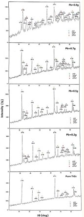
The XRD patt show the participation of all the doped and undoped samples in the titanium dioxide compound with the peaks corresponding to the crystal levels (110), (012), (040), (111), (211), and (211). (123), (112), (220). The preferred orientation is (112) in all pure and lead-doped samples, while the peaks corresponding to levels (210), (213), (160), (203) disappear or shift in The doped sample with a lead content of 0.9 g, while the peak corresponding to level (220) disappears or shifts in the doped sample with a lead content of 0.7 g. It was also observed with the different proportions of the alloy that there is an absence of some peaks corresponding to pure titanium dioxide and the emergence of new peaks due to lead impurity (Figure 2).
Second: titanium dioxide compound doped with iron TiO2: Fe
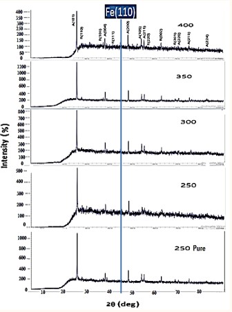
Figure 3 shows the x-ray diffraction (XRD) patterns of the prepared compounds where the sharp and intense peaks in the resulting XRD patterns indicate that the as-prepared compounds are well crystallized. The study of the XRD plots in comparison with the reference card 0001735 in the AMCSD database showed that the studied material is iron-doped titanium oxide that crystallizes in a polycrystalline tetragonal structure, where two
Figure 1: Crystal configurations of an anatase, b rutile, and c brookite TiO2. The small red sphere and large blue sphere represent the O and Ti atoms, respectively.
Figure 2: XRD results of pure and lead-doped TiO2 samples with different ratios according to (x = 0.2 – 0.5 – 0.7 – 0.9 g). The dots in green indicate the anatase phase, the dots in blue indicate the brookite phase, the dots in orange indicate the rutile phase, and the dots in red It indicates an impurity of lead.
Figure 3: Plots of x-ray diffraction patterns of pure and iron-doped titanium oxide samples at different rotational speeds.
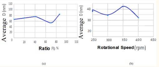
Figure 4: Plots of x-ray diffraction patterns of pure and iron-doped titanium oxide samples at different rotational speeds.
phases of titanium oxide are observed, namely the rutile phase and the anatase phase, and this is consistent with Some studies [19].
The XRD patt show the participation of all the doped and undoped samples in the titanium dioxide compound with the peaks corresponding to the crystal levels (101), (004), (200) which belonged to the anatase phase, while the peaks of the rutile phase varied and were not similar in any of the samples. The preferred orientation is (101) in all pure and iron-doped samples, which belonged to the anatase phase.
As we can see from the diffraction diagrams, Figure 3 that the addition of a proportion of iron leads to the appearance of a distinct peak of iron at the value of the angle 2θ≈45 °. In addition to stability in the two phases formed for all samples in terms of the locations of the diffraction peaks, while we notice a change in the intensity of the anatase peaks in relation to the rutile phase in the samples with the change in the rotation speed. Therefore, by comparison between the pure sample and similar samples, the effect of iron ions on the phases can be observed. Morphed. We also note that doping with iron does not have any significant effect on the phase transition between the anatase to rutile phases. On the other hand, doping with iron can delay or prevent the formation of the rutile phase, in accordance with some studies [35].
In all the pure and iron-doped samples, one iron peak appeared corresponding to the level (110).
We calculated the relative intensity of the pure and leaddominated TiO2 powders. The distance values between crystal planes were calculated using the following Bragg’s law [39]:
2dsinθ = n λ-------------------------------------------------------(3)
Where d is the distance between crystal planes in angström (A°) and θ is Braggs’s angle in radians (rad) and λ is the wavelength of the x-rays (λ = 1.78897 A°) and we calculated the crystallite size from Scherrer’s equation [22]:
Where D is the crystal size in nanometer (nm).
----------------------------------------------------------(4)
K is Scherrer’s constant, so for a cubic crystal system it takes the value 0.94, and for a non-cubic crystal system it takes the value 0.89 and therefore the value we use is the last value [10].
λ is the wavelength of x-rays measured in angstrom (A°)
ß is the full width at half maximum intensity (FWHM) measured in radians. θ is the Braggs’s angle, also measured in radians.
The lattice constants a (A°), b (A°) and c (A°) a for the tetragonal crystal system of the anatase, rutile and orthorhombic crystal
System of the brookite phase was determined from the equations (4) and (5), respectively [30] and [25]:
--------------------------------------(5)
where a = b ≠ c; for anatase and rutile phases.
Table 2: Results of the structural values of pure TiO2 sample.
|
|
|
|
|
|
|
|
|
Lattice constants for phases |
|
||
|
Sample |
θ2 |
(hkl) |
(A°)d |
Rel.Int. |
β |
(nm)D |
(nm) |
|
Phases cell size |
||
|
|
(deg) |
|
|
(%) |
(deg) |
|
D |
|
V (A°)3 |
||
|
|
|
|
|
|
|
|
|
(A°)a |
(A°)b |
(A°)c |
|
|
|
32.1 |
-110 |
3.236 |
100 |
0.4 |
23.732 |
|
|
|
|
|
|
|
42.355 |
-12 |
2.477 |
25 |
0.355 |
27.559 |
118.236 |
|
|
|
|
|
|
46 |
-40 |
2.29 |
5 |
0.3 |
33.035 |
Anatase |
3.794 |
3.794 |
9.408 |
135.352 |
|
Pure Tio2 |
48.5 |
-111 |
2.178 |
25 |
0.4 |
25.014 |
|
|
|
|
Anatase |
|
|
51.8 |
-210 |
2.048 |
10 |
0.2 |
50.706 |
40.303 |
|
|
|
|
|
|
64.4 |
-211 |
1.679 |
60 |
0.25 |
43.123 |
Brookite |
5.539 |
9.16 |
5.139 |
260.74 |
|
|
67 |
-220 |
1.621 |
20 |
0.4 |
27.35 |
|
|
|
|
Brookite |
|
|
71 |
-123 |
1.541 |
7 |
0.25 |
44.822 |
35.08 |
|
|
|
|
|
|
73.7 |
-213 |
1.492 |
4 |
0.1 |
114.003 |
Rutile |
|
|
|
|
|
|
74.9 |
-160 |
1.472 |
4 |
0.2 |
57.456 |
64.54 |
4.577 |
4.577 |
2.946 |
61.72 |
|
|
76.2 |
-203 |
1.45 |
12 |
0.3 |
38.642 |
For |
|
|
|
Rutile |
|
|
83 |
-112 |
1.35 |
12 |
0.3 |
40.602 |
Phases |
|
|
|
|
|
|
83.7 |
-220 |
1.341 |
60 |
0.1 |
122.468 |
Together |
|
|
|
|
Table 3: results of the structural values of the lead-doped TiO2 sample (x = 0.2 g).
|
|
|
|
|
|
|
|
|
Lattice constants for phases |
|
||
|
Sample |
θ2 |
(hkl) |
(A°)d |
Rel.Int. |
β |
(nm)D |
(nm) |
|
Phases cell size |
||
|
(A°)c |
(deg) |
|
|
(%) |
(deg) |
|
D |
|
V (A°)3 |
||
|
|
|
|
|
|
|
|
|
(A°)a |
(A°)b |
(A°)c |
|
|
|
32.1 |
-100 |
3.236 |
100 |
0.425 |
22.355 |
|
|
|
|
|
|
|
33.6 |
-110 |
3.095 |
100 |
0.03 |
317.642 |
|
|
|
|
|
|
|
36.7 |
-100 |
2.842 |
75 |
0.1 |
96.113 |
|
|
|
|
|
|
|
37.4 |
-100 |
2.79 |
75 |
0.2 |
48.155 |
82.696 |
3.793 |
3.793 |
9.408 |
135.352 |
|
|
42.36 |
-12 |
2.477 |
25 |
0.3 |
32.612 |
Anatase |
|
|
|
Anatase |
|
|
46 |
-40 |
2.29 |
5 |
0.18 |
55.058 |
|
|
|
|
|
|
Lead - |
48.5 |
-111 |
2.178 |
25 |
0.5 |
20.011 |
|
|
|
|
|
|
Doped |
51.8 |
-210 |
2.048 |
10 |
0.1 |
101.412 |
47.849 |
|
|
|
|
|
Tio2 |
57.7 |
-210 |
1.854 |
10 |
0.2 |
52.077 |
Brookite |
|
|
|
|
|
(x=0.2g) |
64.4 |
-211 |
1.679 |
60 |
0.3 |
35.936 |
|
|
|
|
|
|
|
67 |
-220 |
1.621 |
20 |
0.24 |
45.583 |
|
5.539 |
9.16 |
5.146 |
261.094 |
|
|
71 |
-123 |
1.541 |
7 |
0.18 |
62.253 |
|
|
|
|
Brookite |
|
|
71.9 |
-512 |
1.524 |
5 |
0.24 |
46.954 |
83.105 |
|
|
|
|
|
|
72.4 |
-103 |
1.515 |
20 |
0.12 |
94.207 |
Rutile |
|
|
|
|
|
|
73.7 |
-213 |
1.492 |
4 |
0.18 |
63.335 |
|
4.577 |
4.577 |
2.945 |
61.695 |
|
|
74.9 |
-160 |
1.472 |
4 |
0.18 |
63.839 |
71.217 |
|
|
|
Rutile |
|
|
76.2 |
-203 |
1.45 |
12 |
0.22 |
52.694 |
For |
|
|
|
|
|
|
83 |
-112 |
1.35 |
12 |
0.28 |
43.502 |
Phases |
|
|
|
|
|
|
83.7 |
-220 |
1.341 |
6 |
0.12 |
102.057 |
together |
|
|
|
|
Where d is the distance between two successive one angstroms of crystal planes in angstroms (A°) and (hkl) are the Miller indices. The grid constants a (A°), b (A°) and c (A°) a given in Tables 1-3 were also calculated, which match well with the JCPDS data. Were also calculated, for brookite, (a = 5.455 A°, b = 9.18 A°, c = 142 A°), and for rutile (a = b = 4.593 A°, c = 2.959A°), and for anatase (a= b = 3.785 A°, c = 9.513 A°), and for lead Pb(a= b=3.265 A°, c = 5.387 A°). The change in peak intensity is mainly due to the replacement of Ti+4 ions by Pb+4 ions in the TiO2 lattice. We also computed initial cell size from equation [1]:
V = a. b. c---------------------------------------------------------------(6)
Where a, b, c are the crystal lattice constants given in A°.
First: titanium dioxide compound doped with lead TiO2: Pb
From these tables we can conclude the following:
1- The possibility of preparing a lead-doped TiO2 compound using the solid-state reaction method by doping it with different ratios
x= 0.2, 0.5, 0.7, 0.9 g) and the possibility of preparing a TiO2 compound doped with iron at an alloying ratio of (x = 10% and for different rotational speeds (250, 300, 350, 400 rpm) and for a period of 5h.
2- The distance values between two successive crystalline planes d(A°) correspond to each of the TiO2 compound doped with lead using the solid state reaction method by doping it with different proportions and the TiO2 compound doped with iron at a doping ratio of x = 10% and for different rotational speeds.
3- The XRD diagrams of TiO2 : Pb prepared by solid state reaction method as a function of different doping ratios and TiO2 : Fe prepared by ball milling method as a function of rotational speed show that their structural properties change due to the influence of positive ions (Pb4+) and (Fe3+), where we notice that the volume of crystallization increases with the increase in the percentage of doping with lead. We also notice with the increase in the percentage of doping.
New peaks appeared for the three phases and for lead
Where the mixing time is five hours for all samples.
impurity. A noticeable displacement in the positions of the peaks of the powders prepared after the doping process, and that this displacement tends towards greater values of (θ2) with the increase in the percentage of doping, and the explanation for this displacement is due to the small ionic radius (Ionic radius) of titanium (0.68 Å) [21]. Compared to the ionic radius of lead impurity (0.940 Å) [23], this impurity replaces titanium as a substitution atom without occupying the interfacial sites because it has an ionic radius greater than (0.8 Å), which leads to a decrease in the size of the TiO2 crystal because of the decrease in the distance between the crystalline levels ( d) and then an increase in the diffraction angle That is, the displacement of the distinct peaks towards the right in the diffraction pattern due to its association with an inverse relationship according to Bragg’s law [40] as stipulated in Pauling’s principle [30,31,33],
while the crystallization size decreases when iron ions are introduced into the titanium oxide structure, due to the small ion radius of iron compared to the titanium ion, where (Fe3+)=0.64Å, (Ti4+)=0.68Å, and then The crystallization volume again increases with the increase in spin speed.
4- It was observed that with increasing the percentage of lead contamination, the size of the primary cell and the relative intensity increased, and this resut consistents with the researcher Hu MZ [31].
Table 4: results of the structural values of TiO2 sample doped with lead (x = 0.5 g).
|
|
|
|
|
|
|
|
|
|
Phases cell size |
||
|
Sample c (A°) |
2θ (deg) |
(hkl) |
d (A°) |
Rel.Int.(%) |
β (deg) |
D (nm) |
D (nm) |
Lattice constants for phases |
|||
|
|
|
|
|
|
|
|
|
|
V (A°)3 |
||
|
|
|
|
|
|
|
|
|
(A°)a |
(A°)b |
(A°)c |
|
|
|
32.1 |
-110 |
3.236 |
100 |
0.3 |
31.642 |
|
|
|
|
|
|
|
33.6 |
-110 |
3.095 |
100 |
0.3 |
31.765 |
|
3.793 |
3.793 |
9.408 |
135.352 |
|
|
36.7 |
-100 |
2.842 |
75 |
0.05 |
192.226 |
88.324 |
|
|
|
Anatase |
|
|
37.4 |
-100 |
2.79 |
75 |
0.2 |
48.155 |
Anatase |
|
|
|
|
|
|
42.355 |
-12 |
2.477 |
25 |
0.2 |
48.917 |
|
|
|
|
|
|
|
46 |
-40 |
2.29 |
5 |
0.2 |
49.552 |
|
|
|
|
|
|
|
48.5 |
-111 |
2.178 |
25 |
0.3 |
33.352 |
99.547 |
5.539 |
9.16 |
5.146 |
261.094 |
|
Lead - Doped Doped Tio2 (x=0.5g) |
51.8 |
-210 |
2.048 |
10 |
0.1 |
101.412 |
Brookite |
|
|
|
Brookite |
|
52.3 |
-411 |
2.03 |
7 |
0.1 |
101.628 |
|
|
|
|
|
|
|
57.7 |
-132 |
1.854 |
18 |
0.4 |
26.039 |
|
|
|
|
|
|
|
64.4 |
-211 |
1.679 |
60 |
0.2 |
53.904 |
|
|
|
|
|
|
|
|
67 |
-220 |
1.621 |
20 |
0.1 |
109.398 |
48.382 |
|
|
|
|
|
|
71 |
-103 |
1.541 |
20 |
0.15 |
74.704 |
Rutile |
|
|
|
|
|
|
72.4 |
-103 |
1.515 |
20 |
0.08 |
141.311 |
|
|
|
|
|
|
|
73.7 |
-213 |
1.492 |
4 |
0.12 |
95.002 |
|
4.577 |
4.577 |
2.945 |
61.695 |
|
|
74.9 |
-160 |
1.472 |
4 |
0.05 |
229.821 |
78.752 |
|
|
|
Rutile |
|
|
76.2 |
-203 |
1.45 |
12 |
0.2 |
57.963 |
For |
|
|
|
|
|
|
83 |
-112 |
1.35 |
12 |
0.2 |
60.559 |
Phases |
|
|
|
|
|
|
83.7 |
-220 |
1.341 |
6 |
0.15 |
81.646 |
Together |
|
|
|
|
Table 5: results of the structural values of TiO2 sample doped with lead (x = 0.7 g).
|
Sample c (A°) |
2θ (deg) |
d (hkl) |
(A°) |
Rel.Int.(%) |
β (deg) |
D(nm) |
D (nm) |
phases |
Phases cell size |
||
|
|
|
|
|
|
|
|
|
(A°)a |
(A°)b |
(A°)c |
|
|
|
32.1 |
-110 |
3.236 |
100 |
0.3 |
31.642 |
|
|
|
|
|
|
|
33.6 |
-110 |
3.095 |
100 |
0.6 |
15.883 |
|
|
|
|
|
|
|
36.7 |
-100 |
2.842 |
75 |
0.3 |
32.038 |
89.735 |
|
|
|
|
|
|
37.4 |
-100 |
2.79 |
75 |
0.4 |
24.078 |
Anatase |
|
|
|
|
|
|
42.355 |
-12 |
2.477 |
25 |
0.3 |
32.611 |
|
3.793 |
3.793 |
9.408 |
135.352 |
|
|
46 |
-40 |
2.29 |
5 |
0.4 |
24.776 |
|
|
|
|
Anatase |
|
|
48.5 |
-111 |
2.178 |
25 |
0.24 |
41.69 |
49.802 |
|
|
|
|
|
|
51.8 |
-210 |
2.048 |
10 |
0.34 |
29.827 |
Brookite |
|
|
|
|
|
|
57.7 |
-132 |
1.854 |
18 |
0.2 |
52.077 |
|
|
|
|
|
|
|
62.3 |
-240 |
1.73 |
3 |
0.2 |
53.298 |
|
|
|
|
|
|
Lead - Doped Tio2 (x=0.7g) |
64.4 |
-211 |
1.679 |
60 |
0.21 |
51.337 |
|
5.539 |
9.16 |
5.146 |
261.094 |
|
66.4 |
-110 |
1.634 |
70 |
0.1 |
109.022 |
|
|
|
|
Brookite |
|
|
67 |
-220 |
1.621 |
20 |
0.4 |
27.35 |
|
|
|
|
|
|
|
70 |
-123 |
1.59 |
7 |
0.1 |
111.366 |
32.598 |
|
|
|
|
|
|
|
71 |
-123 |
1.541 |
7 |
0.4 |
28.014 |
Rutile |
|
|
|
|
|
|
71.9 |
-103 |
1.524 |
20 |
0.12 |
93.908 |
|
|
|
|
|
|
|
72.4 |
-103 |
1.515 |
20 |
0.21 |
53.833 |
|
4.577 |
4.577 |
2.945 |
61.695 |
|
|
73.7 |
-213 |
1.492 |
4 |
0.2 |
57.002 |
|
|
|
|
Rutile |
|
|
74.9 |
-160 |
1.472 |
4 |
0.3 |
38.304 |
|
|
|
|
|
|
|
76.2 |
-203 |
1.45 |
12 |
0.2 |
57.963 |
57.379 |
|
|
|
|
|
|
79.5 |
-112 |
1.399 |
35 |
0.2 |
59.327 |
For |
|
|
|
|
|
|
83 |
-112 |
1.35 |
12 |
0.4 |
30.451 |
phases |
|
|
|
|
|
|
83.7 |
-220 |
1.341 |
6 |
0.1 |
122.468 |
together |
|
|
|
|
Table 6: results of the structural values of TiO2 sample doped with lead (x = 0.9 g).
|
Sample |
2θ (deg) |
(hkl) |
d (A°) |
Rel.Int.(%) |
β (deg) |
D (nm) |
D (nm) |
Lattice constants for phases |
Phases cell size |
||
|
|
|
|
|
|
|
|
|
(A°)a |
(A°)b |
(A°)c |
|
|
|
32.1 |
-110 |
3.236 |
100 |
0.5 |
18.986 |
|
|
|
|
|
|
|
33.6 |
-110 |
3.095 |
100 |
0.6 |
15.883 |
|
|
|
|
|
|
|
35.7 |
-112 |
2.919 |
90 |
0.2 |
47.92 |
|
|
|
|
|
|
|
36.7 |
-100 |
2.842 |
75 |
0.15 |
64.076 |
|
|
|
|
|
|
Lead - Doped Tio2 x=0.9g)) |
37.4 |
-100 |
2.79 |
75 |
0.1 |
96.31 |
|
|
|
|
|
|
39.6 |
-200 |
2.641 |
30 |
0.2 |
48.479 |
|
3.793 |
3.793 |
9.502 |
136.704 |
|
|
42.355 |
-12 |
2.477 |
25 |
0.2 |
48.917 |
62.565 |
|
|
|
Anatase |
|
|
46 |
-40 |
2.29 |
5 |
0.2 |
49.552 |
Anatase |
|
|
|
|
|
|
|
46.5 |
-112 |
2.266 |
8 |
0.1 |
99.289 |
|
|
|
|
|
|
|
48.5 |
-111 |
2.178 |
25 |
0.26 |
38.483 |
|
|
|
|
|
|
|
52.3 |
-210 |
2.03 |
10 |
0.04 |
254.07 |
|
|
|
|
|
|
|
53.5 |
-32 |
1.988 |
16 |
0.2 |
51.08 |
|
|
|
|
|
|
|
54.5 |
-102 |
1.954 |
10 |
0.21 |
48.864 |
|
|
|
|
|
|
|
57.7 |
-102 |
1.854 |
10 |
0.2 |
52.077 |
|
|
|
|
|
|
|
61.215 |
-240 |
1.757 |
3 |
0.11 |
96.358 |
|
|
|
|
|
|
|
61.25 |
-332 |
1.756 |
26 |
0.08 |
132.515 |
|
|
|
|
|
|
|
64.4 |
-240 |
1.679 |
3 |
0.1 |
107.807 |
94.31 |
5.539 |
9.16 |
5.146 |
263.428 |
|
|
66.4 |
-110 |
1.634 |
70 |
0.2 |
54.511 |
Brookite |
|
|
|
Brookite |
|
|
67 |
-220 |
1.621 |
20 |
0.05 |
218.796 |
|
|
|
|
|
|
|
70 |
-440 |
1.56 |
5 |
0.08 |
139.208 |
|
|
|
|
|
|
|
71 |
-123 |
1.541 |
7 |
0.2 |
56.028 |
|
|
|
|
|
|
|
71.9 |
-512 |
1.524 |
5 |
0.1 |
112.69 |
|
|
|
|
|
|
|
72.4 |
-103 |
1.515 |
20 |
0.1 |
113.049 |
99.233 |
|
|
|
|
|
|
74.9 |
-160 |
1.472 |
4 |
0.2 |
57.456 |
Rutile |
|
|
|
|
|
|
75 |
-600 |
1.47 |
2 |
0.2 |
57.494 |
|
4.577 |
4.577 |
2.945 |
61.695 |
|
|
78.4 |
-611 |
1.416 |
9 |
0.08 |
147.149 |
|
|
|
|
Rutile |
|
|
79.5 |
-112 |
1.399 |
35 |
0.2 |
59.327 |
|
|
|
|
|
|
|
83 |
-112 |
1.35 |
12 |
0.3 |
40.602 |
|
|
|
|
|
|
|
83.7 |
-220 |
1.341 |
6 |
0.2 |
61.234 |
85.37 |
|
|
|
|
|
|
87.6 |
-4 |
1.293 |
2 |
0.1 |
126.393 |
For |
|
|
|
|
|
|
87.8 |
-4 |
1.29 |
2 |
0.05 |
253.211 |
phases |
|
|
|
|
|
|
88.9 |
-107 |
1.278 |
<2 |
0.2 |
63.896 |
together |
|
|
|
|
We noted from Tables 3-5,6 that the 0.2g leads doped TiO2 is the closest value to the undoped sample. Also, doping with lead in different proportions gave values for both cell size and crystallization volume that were almost twice as large compared to the values given by doping the compound with iron at different rotational speeds. As for increasing the rotational speed, the relative intensity increased and the primary cell size decreased for the rutile stage, while it increased for the anatase stage.
The rutile sample with a rotation speed of rpm 300 was the closest value to the pure sample, while the anatase sample had a rotation speed of 900 rpm.
Figure 4 shows that the average crystal size of each sample doped with lead by 0.2g and the sample doped with iron with a rotational speed of rpm 250 is closest to that of the pure sample, but the decrease in the average crystal size increase at 0.7g compared to other doped samples may be due The reason for the linear increase in the average crystal size starting from the pure compound and passing through each of the two percentages of lead doping 0.5g and 0.2g is that the impurities effectively prevent the growth of grains by forming dissimilar border areas and because of the increase in the percentage of doping that causes an increase in the crystal size and this resut agrees with the researcher JIAGUO YU [28], while increasing the rotation speed may be a reason for increasing the growth of these grains, and because of the increase in the rotation speed, the crystal size decreases, so most of the iron-doped titanium dioxide samples
had a lower crystal size with increasing the rotation speed. We know that the increase in particle sizes reduces the stress in the granular boundaries resulting from the crushing process and the rotation process, and these boundaries are suitable places for the locations of crystalline defects and impurities that lead to the enhancement of the electrical resistance, and therefore, the electrical conductivity will increase [39]. For titanium dioxide doped with lead, and on the contrary, for titanium dioxide doped with iron, the decrease in crystalline size was greater than the increase.
This decrease is due to the lack of crystalline defects. And since the phases do not have a difference in chemical composition, while there is a change in the atomic arrangement and crystal orientation across the phase boundaries, the surfaces separating them are not similar in energy and composition to the grain boundaries with a small inclination angle. It is possible that the presence of crystalline defects in the sample with a dopant ratio of 0.7g is the reason for the change in the linear increase, as we noticed a decrease in the crystalline size at (57.379 nm) as it is noticeable in Table 7-9 a decrease in the grain size of each of brookite and rutile except for anatase [22].
Tables 7: distinctive peaks for each of the prepared samples and their structural information:
|
Pure titanium oxide at 250rpm rotating speed |
|
|||||||
|
(A°)d |
2Theta |
I(rel) |
I(abs) |
FWHM |
h k l |
|
||
|
3.516740 |
25.3051 |
100.00 |
1056 |
0.1200 |
A (1 0 1) |
|
||
|
2.432455 |
27.4383 |
21.93 |
232 |
0.0800 |
R (1 1 0) |
|
||
|
2.379274 |
36.9240 |
19.30 |
204 |
0.0200 |
A (1 0 3) |
|
||
|
2.333727 |
37.7802 |
28.88 |
305 |
0.1400 |
A (0 0 4) |
|
||
|
1.893597 |
38.5464 |
22.03 |
233 |
0.0400 |
A (1 1 2) |
|
||
|
1.701379 |
48.0069 |
34.07 |
360 |
0.1200 |
A (2 0 0) |
|
||
|
1.667346 |
53.8405 |
27.49 |
290 |
0.0800 |
R (2 1 1) |
|
||
|
1.481433 |
55.0313 |
26.65 |
282 |
0.1000 |
A (2 1 1) |
|
||
|
1.364906 |
62.6603 |
22.03 |
233 |
0.1400 |
A (2 0 4) |
|
||
|
1.265659 |
68.7158 |
16.57 |
175 |
0.0800 |
A (1 1 6) |
|
||
|
2.432455 |
74.9788 |
17.72 |
187 |
0.1200 |
A (2 1 5) |
|
||
|
Iron doped titanium oxide at 250rpm rotational speed |
|
|||||||
|
(A°)d |
2Theta |
I(rel) |
I(abs) |
FWHM |
h k l |
|
||
|
3.518577 |
25.2916 |
100.00 |
511 |
0.1200 |
A (1 0 1) |
|
||
|
2.380515 |
37.7597 |
37.44 |
191 |
0.0800 |
A (0 0 4) |
|
||
|
2.028429 |
44.6366 |
36.43 |
186 |
0.2600 |
Fe (1 1 0) |
|
||
|
1.893746 |
48.0028 |
44.33 |
227 |
0.0800 |
A (2 0 0) |
|
||
|
Iron doped titanium oxide at 300rpm rotational speed |
|
|||||||
|
(A°)d |
2Theta |
I(rel) |
I(abs) |
FWHM |
h k l |
|
||
|
3.518911 |
25.2892 |
100.00 |
802 |
0.1400 |
A (1 0 1) |
|
||
|
2.380958 |
37.7525 |
38.81 |
311 |
0.1200 |
A (0 0 4) |
|
||
|
2.030406 |
44.5908 |
28.43 |
228 |
0.1200 |
Fe (1 1 0) |
|
||
|
1.893879 |
47.9993 |
39.62 |
318 |
0.1600 |
A (2 0 0) |
|
||
|
1.701409 |
53.8395 |
33.16 |
266 |
0.1400 |
A (1 0 5) |
|
||
|
1.667941 |
55.0100 |
31.80 |
255 |
0.1200 |
A (2 1 1) |
|
||
|
1.482349 |
62.6172 |
30.31 |
243 |
0.0600 |
A (2 0 4) |
|
||
|
1.266013 |
74.9543 |
23.95 |
192 |
0.0800 |
R (3 2 0) |
|
||
|
Iron doped titanium oxide at 350rpm rotational speed |
||||||||
|
(A°)d |
2Theta |
I(rel) |
I(abs) |
FWHM |
h k l |
|||
|
3.513264 |
25.3305 |
100.00 |
1325 |
0.1200 |
A (1 0 1) |
|||
|
3.243978 |
27.4728 |
19.80 |
262 |
0.0800 |
R (1 1 0) |
|||
|
2.430325 |
36.9575 |
19.42 |
257 |
0.0800 |
A (1 0 3) |
|||
|
2.377405 |
37.8110 |
31.10 |
412 |
0.1000 |
A (0 0 4) |
|||
|
2.331508 |
38.5845 |
18.72 |
248 |
0.1200 |
A (1 1 2) |
|||
|
2.026722 |
44.6762 |
19.41 |
257 |
0.1000 |
Fe (1 1 0) |
|||
|
1.892357 |
48.0403 |
36.83 |
488 |
0.1400 |
A (2 0 0) |
|||
|
1.700474 |
53.8714 |
28.16 |
373 |
0.1400 |
A (1 0 5) |
|||
|
1.666796 |
55.0510 |
28.04 |
371 |
0.1600 |
A (2 1 1) |
|||
|
1.481313 |
62.6660 |
23.98 |
318 |
0.1400 |
A (2 0 4) |
|||
|
1.364488 |
68.7398 |
16.92 |
224 |
0.1800 |
A (1 1 6) |
|||
|
1.338632 |
70.2605 |
18.22 |
241 |
0.0600 |
A (2 2 0) |
|||
|
1.265157 |
75.0138 |
20.16 |
267 |
0.1200 |
A (2 1 5) |
|||
|
1.166743 |
82.6322 |
17.51 |
232 |
0.0400 |
R (3 2 1) |
|||
|
Iron doped titanium oxide at 400rpm rotational speed |
||||||||
|
(A°)d |
2Theta |
I(rel) |
I(abs) |
FWHM |
h k l |
|||
|
3.517184 |
25.3018 |
100.00 |
400 |
0.1400 |
A (1 0 1) |
|||
|
2.379251 |
37.7806 |
40.24 |
161 |
0.1200 |
A (0 0 4) |
|||
|
2.023055 |
44.5720 |
39.88 |
160 |
0.1600 |
Fe (1 1 0) |
|||
|
1.893844 |
48.0002 |
48.88 |
195 |
0.1600 |
A (2 0 0) |
|||
|
1.700793 |
53.8605 |
39.09 |
156 |
0.0800 |
A (1 0 5) |
|||
|
1.667824 |
55.0142 |
38.92 |
156 |
0.1000 |
A (2 1 1) |
|||
|
1.481543 |
62.6552 |
33.18 |
133 |
0.0800 |
R (0 0 2) |
|||
Table 8: primary cell parameters of samples for the anatase phase.
|
Sample |
Rotational speed |
Lattice constants for phases |
Phases cell size |
|
|
|
|
rpm |
co (Å) |
ao (Å) |
V (Å3) |
D (nm) |
|
|
250 |
9.4283 |
3.7876 |
135.2585 |
46.4699 |
|
|
250 |
9.5355 |
3.7876 |
136.796 |
38.6515 |
|
|
300 |
9.5593 |
3.7861 |
137.03 |
40.6858 |
|
|
350 |
9.4513 |
3.7861 |
135.482 |
50.619 |
|
|
400 |
9.4815 |
3.7876 |
136.021 |
44.7561 |
Table 9: Primary cell parameters of samples for the rutile phase.
|
Sample |
Rotational speed |
Lattice constants for phases |
Phases cell size |
Crystal size |
|
|
|
rpm |
co (Å) |
ao (Å) |
V (Å3) |
D (nm) |
|
pure |
250 |
2.0962 |
4.5962 |
44.2833 |
30.5021 |
|
|
250 |
2.095 |
4.5092 |
42.5973 |
38.8659 |
|
|
300 |
2.0962 |
4.5962 |
44.2833 |
28.4686 |
|
|
350 |
2.095 |
4.5831 |
44.0057 |
35.5918 |
|
|
400 |
2.0956 |
4.5929 |
44.2073 |
20.3356 |
The crystal size of the three phases of the compound doped with lead together falls within the range [57.379-85.370 nm], distributed into anatase [62.565-118.236 nm], brookite [40.303-94.310 nm] and rutile [35.080-99.233 nm] and this resut consistents with the researcher Fouzia [34,41], as for the iron-doped compound,
the crystalline size belongs to the range [38.6515-50.6190 nm] for the anatase phase, while for rutile it falls within the range [20.3356-38.8659 nm], where the grain size of the iron-doped compound was almost twice as small as the grain size of the lead doped compound.
CONCLUSION
The XRD plots of TiO2 : Pb prepared by solid-state reaction as a function of different doping ratios and TiO2 : Fe prepared by ball milling as a function of rotational speed showed that their structural properties change due to the influence of positive ions (Pb4+) and (Fe3+). These structural properties explain some physical properties of TiO2 powders doped with lead in different proportions and doped with iron at different rotational speeds. The results of the XRD for the compound doped with lead showed that the samples of anatase and rutile with a tetragonal crystal system and brookite with a rhomboid crystal system based in a compound of titanium dioxide have peaks corresponding to the crystal levels (110), (012), (040), (111), (211), (123), (112), (220).
All samples prefer the direction along the plane (211). As for the compound doped with iron, the common crystal levels for all the doped and undoped samples were (110), (101), (004), (111), (200), (105), (211), (220), (002), (301), (220), (215), (224) and that all samples prefer the direction according to the plane (101), and the average crystal size (D) of the compound doped with lead for the three phases together falls within the range [57.379- 85.370 nm], and within the field [32.54585-38. 7587 nm] for the compound doped with iron for the anatase and rutile phases. And by calculating the distance between the crystalline planes (d), the lattice parameters a)), (b) and c) and the cell size of the phases (V), which fell within the range [61.6950 -261.0940 nm] for the compound doped with lead and within the range [42.5973- 137.0300 nm] for the iron-doped compound. The values of the network constants a (A°), b (A°) and c (A°) for all samples were almost identical to the JCPDS values.
REFERENCES
- Schneider J, Matsuoka M, Takeuchi M, Zhang J, Horiuchi Y, Anpo M, et al. Understanding TiO2 Photocatalysis: Mechanisms and Materials. Chem Rev. 2014; 114: 9919–9986.
- Paola AD, Ikeda S, Marcì G, Ohtani B, Palmisano L. Transition metal doped TiO?: physical properties and photocatalytic behavior. Int J Photoenergy. 2001; 3.
- Zakrzewska K, Radecka M, Rekas M. Effect of Nb, Cr, Sn Additions on Gas Sensing Properties of TiO 2 Thin Films. Thin Solid Films 1997; 310: 161-166.
- Long R, Dai Y, Meng g, Huang B. Energetic and electronic properties of X- (Si, Ge, Sn, Pb) doped TiO2from first-principles. Phys Chem Chem Phys. 2009; 11: 8165-8172.
- Yu-Chao Tang, Xian-Huai H, Yu HQ, Tang LH. Nitrogen-Doped TiO2Photocatalyst Prepared byMechanochemical Method: Doping Mechanisms and Visible Photoactivity of Pollutant Degradation. Int J Photoenergy. 2012.
- Lutic D, Petrovschi D, Ignat M, Cre?escu I, Bulai G. Mesoporous cerium-doped titania for the photocatalytic removal of persistent dyes. Catal Today. 2018; 306: 300–309.
- Li B, Cheng X, Yu X, Yan L, Xing Z. Synthesis and Characterization of Fe-N-S-tri-Doped TiO2Photocatalyst and Its Enhanced Visible Light Photocatalytic Activity. Adv Mater Sci Eng. 2012.
- Paola AD, Bellardita M, Palmisano L. Brookite, the Least Known TiO2 Photocatalyst. Cataiysts. 2013; 3: 36-73.
- Pérez E, Vittorio L, Torres MF, Sham E. Nitrogen doped TiO? photoactivein visible light. 2015; 561-570.
- Murcia Mesa JJ, Guarín Romero JR, Cely Macías AC, Rojas Sarmiento HA, Cubillos Lobo JA, Hidalgo López MDC, et al. Methylene blue degradation over M-TiO2 photocatalysts (M= Au or Pt). Degradación de azul de metileno sobre fotocatalizadores M-TiO2 (M = Au o Pt). Cienc en Desarro. 2017; 8: 109-117.
- Maimaiti M, Binhao Z, Mamat M, Tuersun Y, Mijiti A, Wang Q, et al. The Structural, Optical and Photocatalytic Properties of the TiO2 Thin Films. Mater Res Express. 2019; 6.
- Aleksandra P, Janus M, Szymanski K, Mozia S. C-, N- and S-Doped TiO2 Photocatalysts: A. 2021; 11: 144.
- Sun Z, Khlusov IA, Evdokimov KE, Konishchev ME, Kuzmin OS, Khaziakhmatova OG, et al. Nitrogen-doped titanium dioxide films fabricated via magnetron sputtering for vascular stent biocompatibility improvement. J. Colloid Interface Sci. 2022; 626: 101-112.
- Eidsvåg H, Bentouba S, Vajeeston P, Yohi S, Velauthapillai D. TiO2 as a Photocatalyst for Water Splitting—An Experimental and Theoretical Review. Molecules. 2021; 26: 1687
- CardosoJC, Bessegato GG, Zanoni MVB. Efficiency comparison of ozonation, photolysis, photocatalysis and photoelectrocatalysis methods in real textile wastewater decolorization. Water Res. 2016; 98: 39–46.
- Obina WM, Supriyanto A, Cari C, Sumardiasih S, Septiawan TY. Time Variation of Insertion Cu on TiO2 Nanoparticles Layer through the Electroplating Method in Dye-Sensitized Solar Cell (DSSC). J Phys: Theor Appl. 2017; 1, 2: 137-144.
- Madjene F, Aoudjit L, Igoud S, Lebik H, Boutra B. A review: Titanium dioxide photocatalysis for water treatment. Trans. J Sci Technol. 2013; 3: 1857–8047.
- Colmenares Q, Carlos J. Ultrasound and photochemical procedures for nanocatalysts preparation: application in photocatalytic biomass valorization. J Nanosci Nanotechnol. 2013; 13: 4787–4798.
- Carneiro JO, Azevedo S, Fernandes F, Freitas E, Pereira M, Tavares CJ, et al. Synthesis of iron-doped TiO2 nanoparticles by ball-milling process: the influence of process parameters on the structural, optical, magnetic, and photocatalytic properties. J Mater Sci. 2014; 49: 7476–7488.
- Vinila VS, Jacob R, Mony A, Nair HG, Issac S, Rajan S, et al. XRD Studies on Nano Crystalline Ceramic Superconductor PbSrCaCuO at Different Treating Temperatures. Cryst struct theory appl. 2014; 3: 1-9.
- Li L, Liu X, Li R, Wang S. The Influence of Ti4+ Doping on the Elictrical Conductivity and Sythetic Kinetics of NiFe2O4 Powders. Metall Mater Trans E. 2014; 1: 2-7.
- Batttisha IK, Ahmad Farag IS, Kamal M, Ahmad MA, Girgis E, Hesham Azmi EM, et al. Structural, Magnetic and Dielectric Properties of Fe-
- Elhalil A, Elmoubarki R, Sadiq M, Abdennouri M, Kadmi Y, Favier L, et al. Enhanced photocatalytic degradation of caffeine as a model pharmaceutical pollutant by Ag-ZnO-Al2O3 nanocomposite. Desalin Water Treat. 2017; 94: 254–262.
- Long R, Dai Y, Meng g, Huang B. Energetic and electronic properties of X- (Si, Ge, Sn, Pb) doped TiO2from first-principles. Phys Chem Chem Phys. 2009; 11: 8165-8172.
- Yu J, Cheng B, Zhao X, Yu JC. Photocatalytic Activity and Characterization of the Sol-Gel Derived Pb-Doped TiO2Thin Films. J Sol-Gel Sci Tech. 2002; 24: 39-48.
- Kumar K, Sreekanth T, Solid State Physics. Chapter 10. 2005; 214- 2016.
- Hamadanian M, Reisi-Vanani A, Majedi A, Preparation and characterization of S-doped TiO2 nanoparticles, effect of calcination temperature and evaluation of photocatalytic activity. Mat Chem Phys. 2009; 116: 376–382.
- Hu M, Lai P, Bhuiyan MS, Tsouris C. Synthesis and characterization of anodized titanium-oxide nanotube arrays. J Mater Sci. 2009; 44: 2820–2827.
- Akpan UG, Hameed BH. The Advancements in sol–gel Method of Doped-TiO2 Photocatalysts. Appl Catal A: Gen. 2010; 375: 1–11.
- Abbas F, Bensaha R. Optical Properties of Lead Doped Titanium Oxide of Thin Films Prepared by Sol-Gel Method at Low Temperature. U J Mate Sci. 2019; 7: 25-33.
- Moalej NS, Ahadi S, Sheibani S. Photocatalytic degradation of methylene blue by 2w% Fe doped TiO2 nanopowder under visible light irradiation. J Ultrafine Grained Nanostruct Mater. 2019; 52: 133- 141.
- Chatel G, Valange S, Behling R, Colmenares JC. A combined approach using sonochemistry and photocatalysis: how to apply sonophotocatalysis for biomass conversion?. Chem Cat Chem. 2017; 9: 2615–2621.
- Kiss AA, Geertman R, Wierschem M, Skiborowski M, Gielen B, Jordens J, et al. Ultrasound-assisted emerging technologies for chemical processes. J Chem Technol Biotechnol. 2017; 93: 1219–1227.
- Myers HP. Introductory to Solid State physics (Superconductivity Co Co-Doped Ba Sr TiO Prepared by Sol-Gel Technique. New j Chapter 13). Taylar and Francis. 1990.0.90.13glass ceram. 2014; 4: 19-28.
- Agyei-Dwarko NY. U-Pb geochronology and evolution of Caledonian Nappes in northern Norway. University of Oslo. Norway. 2015.
- Pérez E, Vittorio L, Torres MF, Sham E. Nitrogen doped TiO? photoactivein visible light. 2015; 561-570.
- Francisco Tiago LM, Ribeiro Miranda MA, Dos Santos CM, Marcos Sasaki J. The Scherrer equation and the dynamical theory of X-ray diffraction. Acta Crystallogr A Found Adv. 2016; 72: 385-390.
- Moloantoa RJ. Studies of structural and optical variations of nanosized Tio2 induced by precious metal dopants (Au, Pt, Pd and Ag). Fac sci Agric. 2016.
- Monai M, Montini T, Fornasiero P. Brookite: Nothing New under the Sun?. Catalysts. 2017; 7: 304.
- Ali MA, Preparation and studying of radiation effect on Bi2− xPbxSr2Can−1Cun−yNiyO2n+4+σ high temperature superconductor. MSc thesis, University of Baghdad college of Education for Pure Science. 2018.
- Youssef MG. Solid state physics. Ministry of Higher Education Printing presses. 1987; 1.
