Intravascular Ultrasound Guided Coil Embolization of a Giant Coronary Pseudoaneurysm Using Double Guiding Catheter Technique and Follow-Up Observation by Optical Coherence Tomography
- 1. Department of Cardiovascular Medicine, Nippon Medical School Chiba Hokusoh Hospital, Chiba, Japan
- 2. Department of Cardiovascular Medicine, Nippon Medical School, Tokyo, Japan
Abstract
A coronary artery aneurysm (CAA) is defined as local dilation > 1.5 times of the reference vessel diameter.
Keywords
• Aneurysm
• Embolization
• Imaging
• Stent
CITATION
Ikeda T, Takano M, Miyauchi Y, Asai K (2023) Intravascular Ultrasound-Guided Coil Embolization of a Giant Coronary Pseudoaneurysm Us ing Double-Guiding Catheter Technique and Follow-Up Observation by Optical Coherence Tomography. Ann Vasc Med Res 10(3): 1168.
INTRODUCTION
Among CAAs, true aneurysms mainly originated from atherosclerosis or inflammation, whereas pseudoaneurysms are rare complications of percutaneous coronary intervention, including stent implantation [1]. Although a consensus on the optimal therapy for coronary pseudoaneurysms has not been established, there have been several case reports of endovascular therapy, such as deployment of polytetrafluoroethylene (PTFE)-covered stents or stent-assisted coil embolization [2,3]. In coil embolization, coil detachment is usually performed under fluoroscopy. In our case, the coils were released during intravascular ultrasound (IVUS) record using double-guiding catheter technique. The coils were then released into the pseudoaneurysm in real time and were visualized by IVUS. Moreover, the size reduction of the CAA lumen was demonstrated by follow-up optical coherence tomography (OCT) observation.
CASE PRESENTATION
A 70-year-old man with hypertension and dyslipidemia underwent drug-eluting stent (DES) implantation for a culprit lesion of stable angina in the left anterior descending artery. A giant aneurysm formation (approximately 6.7 mm in diameter and 25.8 mm in length) was detected in the mid-right coronary artery (RCA). He had undergone DES (Cypher™ 3.0/28mm, Cordis Corp, Miami Lakes, FL, USA) implantation in the RCA due to angina 11 years earlier. The DES was completely fractured and the aneurysm was found close to the edges of the separated stent pieces on fluoroscopy and angiography. IVUS revealed the absence of a three-layered structure in the vessel wall and sparse of stent struts in a portion of the CAA [Figure 1].
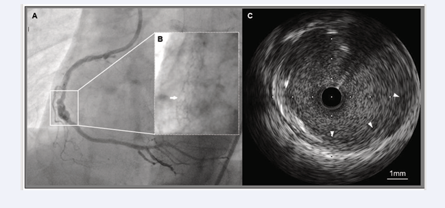
Figure 1: Findings of CAA on fluoroscopy, coronary angiography, and IVUS.
A: Angiography showing a large CAA (surrounded by a square) in the mid-RCA.
B: Complete fracture of the previously implanted DES (white arrow) is observed on fluoroscopy.
C: IVUS within the CAA segment showing sparse stent struts and the absence of a three-layered structure of the arterial walls (white arrowheads).
IVUS guided coil embolization was attempted to prevent rupture of the pseudoaneurysm. First, another 6 Fr Amplatz left catheter was inserted, and two guiding catheters were used: one was for interventions and another for IVUS imaging. A DES (Synergy™ 3.5/28mm, Boston Scientific, Natick, MA, USA) was deployed over the gap between the fractured stents as a bridge. Next, the guidewire, followed by the microcatheter, was advanced into the pseudoaneurysm through the stent struts. Auto-pullback IVUS and fluoroscopy revealed that the microcatheter tip was located within the pseudoaneurysm [Figure 2].
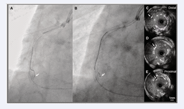
Figure 2: Confirmation of microcatheter position by fluoroscopy and IVUS.
A: Two guiding catheters were used during the procedure. One was for IVUS imaging and the other was for interventions. The guidewire was advanced into the aneurysm sac under fluoroscopic guidance.
B: Subsequently, the microcatheter on the guidewire was inserted into the same space.
C to E: Pullback IVUS images showing the position of the microcatheter (white arrows) shifting from the aneurysm lumen to the stent lumen. These findings indicated that the microcatheter tip was located in the aneurysm sac and external stent lumen.
Finally, 11 coils (Target XL™ Detachable Coils 360 soft, 2.0/30 mm and 2.0/60 mm; Stryker, Kalamazoo, MI, USA) were released into the aneurysmal sac through the microcatheter while IVUS images were recorded [Video].
Video: IVUS movie during coil embolization. Releasing coils as high-echoic dots successively appear in the aneurysm sac.
The appearance of an unusual broken line within the stent lumen prompted a decision regarding the end-point of coil embolization. After the intervention, radiopaque aggregation and many high-echoic dots within the CAA segment were observed on fluoroscopy and IVUS, respectively [Figure 3].
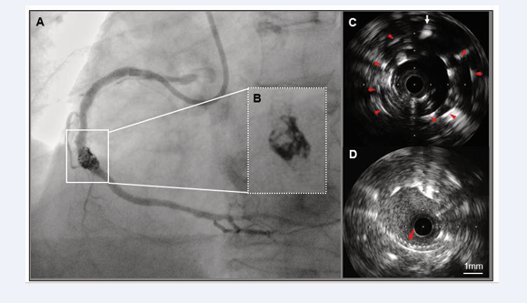
Figure 3: Findings of fluoroscopy, coronary angiography, and IVUS after coiling.
A and B: A radiopaque mass was observed masking the coronary lumen within the CAA segment on angiography.
C: Aside from the microcatheter (white arrow), many high-echoic dots (red arrowheads) are clearly visible in the external stent lumen on negative-contrast IVUS.
D: An unusual broken line (red arrow) appeared into the stent lumen.
Additional OCT observations indicated that the saw-tooth configurations of the coils differed from those of the stent struts.
One year later, follow-up OCT examination was performed despite an uneventful clinical course. Cross-sectional images showed superficial high-intensity tissue with attenuation occupying most of the space around the coils and stent struts. Improvements in both the uneven shape and size reduction of the CAA lumen were observed in longitudinal images [Figure 4].

Figure 4: OCT findings immediately after coiling and at the one-year follow-up.
A: Cross-sectional image obtained immediately after coiling showing saw-tooth configurations (red arrows) in the stent lumen. This cross section likely corresponds to that shown in
Figure 3-D. There are large cavities (white asterisks) between the stent struts/coils and the CAA wall.
B: A dilated lumen with irregularities (white asterisks) was observed within the CAA segment (white double arrow) in the longitudinal image.
C: One year later, most of the stent struts and coils were covered with superficial high-intensity tissue. Most cavities disappeared (blue asterisks); however a few remained (red asterisks). This cross section corresponds to that shown in Figure 4-A.
D: Longitudinal image at follow-up showing that the lumen shape and size within the CAA segment (white double arrow) changed compared to that after coiling (Figure 4-B). Excluding a few regions (red asterisks), the expanded and uneven lumen is mostly improved (blue asterisks).
DISCUSSION
Several mechanisms have been proposed for CAAs after coronary stent implantation [1]. Although the precise mechanism in our case was unclear, mechanical injury of the fractured stent edges to the adjacent vessel walls probably contributed to the pseudoaneurysm formation. Eventually, pseudoaneurysms may rupture and cause life-threatening events [4]. Therefore, endovascular treatment was performed to repair the large pseudoaneurysm. The deployment of a 19 mm PTFE-covered stent (stent graft) was a therapeutic selection. However, due to the length of the pseudoaneurysm neck (measuring 25.8 mm), multiple stent grafts were required for sufficient coverage. Moreover, the overlap of these thick stent grafts narrowed the lumen. Thus, stent-assisted coil embolization was the most suitable procedure in this case.
At the beginning of the stent-assisted coil embolization procedure, a stent is implanted after advancing the microcatheter into the CAA. As a result, the microcatheter is fixed between the stent and the vessel wall, so-called jailed microcatheter [3]. In our case, the order was reversed because the microcatheter would be sandwiched between the fractured and newly implanted stents. In such a situation, it is difficult not only to pass the coils through the crushed microcatheter, but also to remove of the jailed microcatheter after coiling.
The novelty of our case is that the coiling procedure was not performed under fluoroscopy but was guided by IVUS. IVUS was utilized for 1) confirmation of the location of the microcatheter tip in the aneurysmal sac, 2) real-time observation of releasing coils, and 3) decision-making regarding the procedural endpoint. Although the position of the released coils is not completely controllable, IVUS guidance aids in preventing excessive protrusion of the coils into the lumen. IVUS-guided coil embolization requires two guiding catheters which may be complicated for the operator. However, the present technique guarantees both certainly and safety in the coil embolization of CAA.
Follow-up OCT observations showed partial coverage of the stent struts and coils by superficial high-intensity tissue with signal attenuation. Recently, a histopathological study in humans revealed various ages of thrombi, collagen fibers, smooth muscle cells, and infiltration of inflammatory cells around coils in intracranial aneurysms in the chronic phase [5]. Therefore, it was speculated that the tissue consisted of neointima or organized thrombi containing fibrous components according to the OCT findings mentioned above. In any case, changes in the OCT findings over time indicated that tissue growth exhibited a tendency to repair the pseudoaneurysm.
CONCLUSION
In the best of our knowledge, this is the first report of successful IVUS-guided coil embolization of a CAA. Therefore, this method may be an effective treatment option for the patients with CAAs.


